How to bring up the camera and display on a compute module carrier board
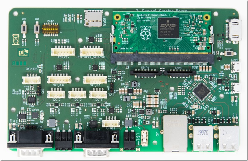
We have developed our own Compute Module Carrier Board, called PCCB. It is compatible with Raspberry Pi Compute Modules 1 – 3 Plus, and has a number of very useful features for industrial use (RS232, CAN Bus, RS485, TPM, DC/DC Stepdown).
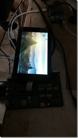
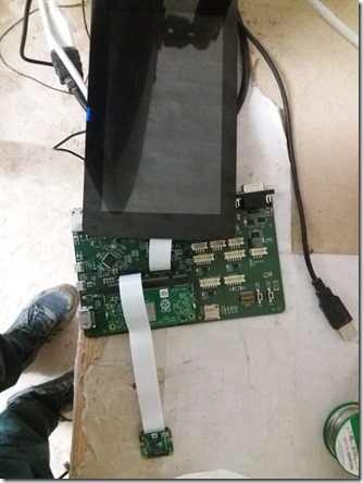
Today, I verified the camera and 7’’ display interface which we provide on the board as well.
Note the DISP1 and CAM1 connectors.
Background knowledge about the camera
The camera module has two additional GPIO Pins. These are designated:
- CAM_IO0 or CAM_GPIO / CAMERA_0_SHUTDOWN
- CAM_IO1 or LED Line / CAMERA_0_LED
CAM_IO0 is used to drive the camera, and power it up / down, when it is required. This can’t be done manually by setting the pin high at runtime – the VideoCore Blob has to be able to do this.
(possibly it is possible to pull this to high always, but this will leave the camera powered and will increase power draw).
The CAM_IO1 (LED Line) was used on the camera v1 previously to drive the LED. It is not in use on Raspberry Pi Camera v2, according to Raspberry Pi engineers.
The pinout of the camera connector (on both the Raspberry Pi Camera and our board) is:
- GND
- CAM_D0_N
- CAM_D0_P
- GND
- CAM_D1_N
- CAM_D1_P
- GND
- CAM_CK_N
- CAM_CK_P
- GND
- CAM_IO0
- CAM_IO1
- CAM_SCL
- CAM_SDA
- CAM_3V3
The camera usually will use the internal I2C bus (SDA0 and SCL0 available, for example, on GPIO0 and GPIO1)
Schematics
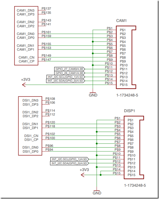
These are the schematics of our hardware layout:
As you can see (and as previously discussed), we are using GPIO_27 as CAM_IO0 and GPIO_26 as CAM_IO1.
The display does not need additional GPIO pins.
Both display and camera use the internal I2C bus, on Pins GPIO_1 and GPIO_0.
dt-blob.bin
This file is an optional part of the Raspberry Pi boot files. It is placed in /boot and overrides a built-in dt-blob.bin which is compiled into start.elf.
It communicates the GPIO pin setup to the Firmware running on the VideoCore (VCOS, Video Core OS). As Compute Module Carrier boards, such as ours, will have custom pin setups, frequently, this dt-blob.bin needs to be provided.
Here is more information on this file, including a step by step boot process:
- https://www.raspberrypi.org/documentation/hardware/computemodule/cm-peri-sw-guide.md
- https://www.raspberrypi.org/documentation/configuration/pin-configuration.md
Raspberry Pi provides the source to several possible setups with the dt-blob.bin here:
I have selected the dt-blob-disp1-cam1.dts file as a source and renamed it to dt-blob-disp1-cam1_pccb.dts.
You can download the original source file from Raspberry Pi here:
This file needs to be modified to reflect our choice of GPIO pins (which in turn will allow the VideoCore Firmware to power up the camera and talk to it).
This source file includes configurations for many different Pi models. We are interested in the compute module configurations only: pins_cm3 and pins_cm
(Note your line numbers may be off by some counters, as I have included some additional things in the file which are not relevant for our discussion here).
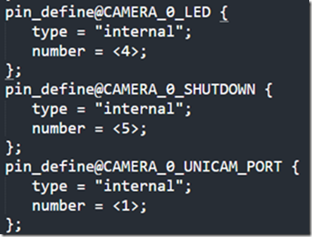
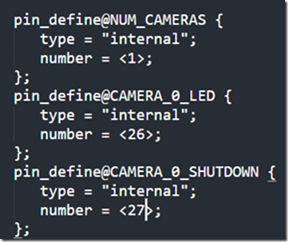
Here you should modify four lines. In our specific (!) hardware setup, I modified:
to
and
to:
The same modifications need to be applied for both CM3 and CM.
pin@p26 { function = “output”; termination = “no_pulling”; }; // CAMERA 0 LED
pin@p27 { function = “output”; termination = “no_pulling”; }; // CAMERA 0 SHUTDOWN(…)
pin_define@CAMERA_0_LED {
type = “internal”;
number = <26>;
};
pin_define@CAMERA_0_SHUTDOWN {
type = “internal”;
number = <27>;
};
pin_define@CAMERA_0_UNICAM_PORT {
type = “internal”;
number = <1>;
};
Note that you also have the possibility to use a different CAMERA_0_I2C_PORT and CAMERA_0_SDA_PIN / CAMERA_0_SCL_PIN if your hardware setup requires it.
The same holds true for the display, there are DISPLAY_SDA, DISPLAY_SCL, DISPLAY_I2C_PORT entries which can be modified.
In our case I have left them at the default, as this is how our board is designed.
Compile this file
On the pi, run:
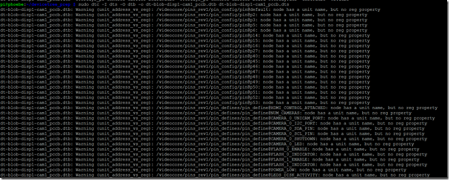
sudo dtc -I dts -O dtb -o dt-blob-disp1-cam1_pccb.dtb dt-blob-disp1-cam1_pccb.dts
This will give you a wall of warnings, which can be safely ignored.
Install dt-blob.bin
sudo cp dt-blob-disp1-cam1_pccb.dtb /boot/dt-blob.bin
And reboot.
Test
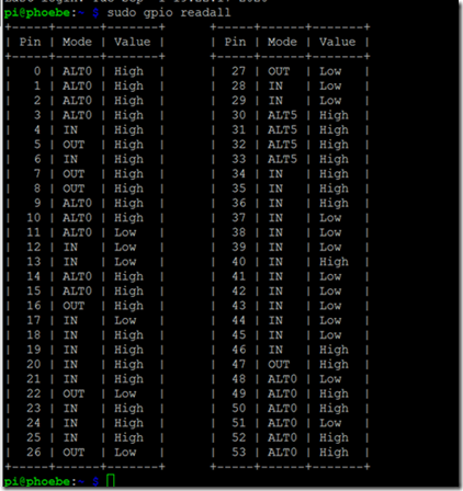
the pins 26 and 27 are now set up as output pins, and are driven low:
vcgencmd get_camera
yields:
supported=1 detected=1
You can take a still using:
raspistill -v -o test.jpg
(Don’t forget to enable the camera using raspi-config as well!)
Video streaming
A little bonus tip. On your Pi, you can start a stream using:
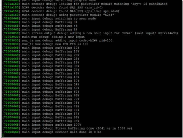
raspivid -o – -t 0 -hf -w 800 -h 400 -fps 24 |cvlc -vvv –h264-fps=24 stream:///dev/stdin –sout ‘#standard{access=http,mux=ts,dst=:8160}’ :demux=h264
Note the –fps 24 and –h264-fps=24 to both raspivid and cvlc, to sync their framerates!
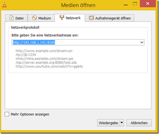
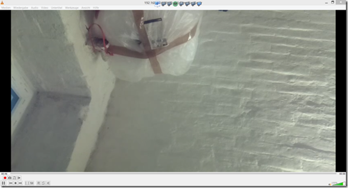
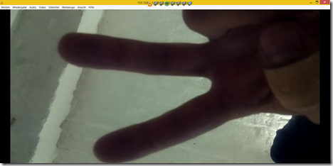
use VLC to view the stream (using your compute board’s IP):
Display
The display also requires the dt-blob.bin.
I used an external power source to power the display, in a revision of the PCCB we will have +5 V power on a header for use with the display.
Please note that I could not use the flex cable from the camera to get the display working; it had to be connected using it’s own (short) cable.
I sequence the power first to the display, then to the PCCB
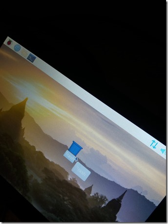
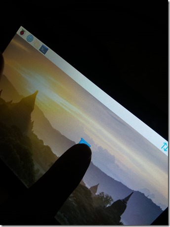
Touch works.
Display & camera together
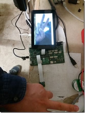
This also works, the camera stream is also displayed live on the display.
Errors
when running
raspistill -v -o test.jpg
you will get:
mmal_vc_component_create: failed to create component ‘vc.ril.camera’ (1:ENOMEM)
also
vcgencmd get_camera
will display either:
supported=0 detected=0
or
supported=1 detected=0
If supported=0 you should check whether your dt-blob.bin is installed correctly in /boot.
If detected=0, you should verify that the GPIO pins are setup correctly in the dt-blob.bin.
Also ensure that the camera is activated using raspi-config.
Proper flex orientation
The flex cables have to be oriented properly to make connection. You can have a look at the pinout, and see if the GND and +3V3 pins behave as expected, or if there is no connection / no voltage.
Service by pi3g
We can bring up your hardware for you, offer consulting services, or bespoke Raspberry Pi hardware and software development – contact us today.
Ref
- https://raspberrypi.stackexchange.com/questions/95420/raspivid-es-out-set-group-pcr-is-called-too-late-stream-keeps-freezing
- https://www.raspberrypi.org/documentation/hardware/display/
- https://raw.githubusercontent.com/raspberrypi/documentation/master/hardware/computemodule/dt-blob-disp1-cam1.dts
- https://www.raspberrypi.org/forums/viewtopic.php?t=164987 (this has the explanation about what the CAM_IO0 and CAM_IO1 lines are used for)
- https://raspberrypi.stackexchange.com/questions/72549/how-can-i-enable-both-the-cameras-on-the-compute-module-3

