
Raspberry Pi Compute Module 4 vs Compute Module 3
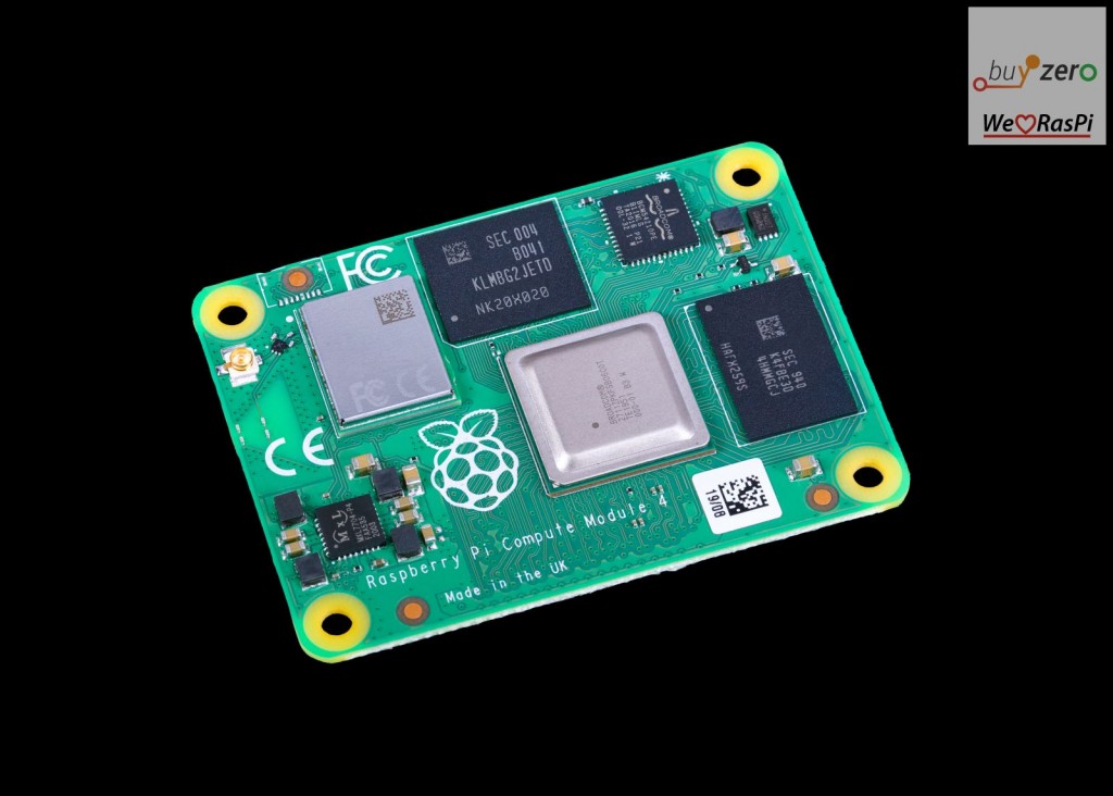
Raspberry Pi launched Compute Module 4, as a successor to Compute Module 3B+. The Compute Module 4 (CM4) is a so-called System on Module (SoM), which contains core parts which make up a Raspberry Pi 4, for example, and in addition to that eMMC Flash in different sizes (ranging from none for the Lite module version to 32 GB).
The CM4 allows designers to integrate a powerful computing solution into their embedded products, without having to sign NDAs with Broadcom, commit to high SoC purchase volumes. They also benefit of the design experience of the Raspberry Pi hardware and software design team, and of course of the Raspberry Pi community and broad range of software support for the Raspberry Pi platform.
Top differences in the new Compute module generation
new form factor
Instead of being DDR2-SODIMM mechanically compatible, such as all previous Compute Modules (1, 3, 3+), the new CM4 connects to your compute module carrier board using two 100-pin high density Hirose connectors.
This allows it to have a smaller footprint (55 mm x 40 mm x 4.7 mm, with 4 x M2.5 mounting holes), and provide new high-speed interfaces. (Raspberry Pi would otherwise have run out of pins with the DDR2-SODIMM approach!)
new capabilities and interfaces
The new CM4 has additional interfaces:
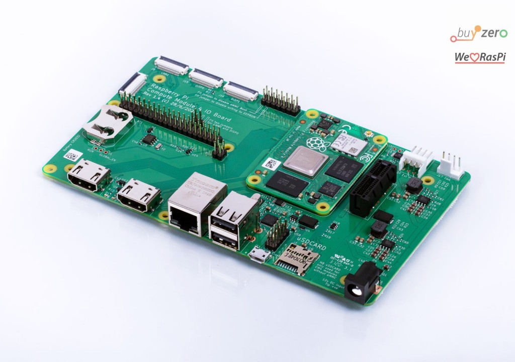
- an additional HDMI port; both HDMI ports are capable of 4K output, and support HDMI 2.0
- PCI Express Interface ( Gen 2 x1 = single lane)
- GBit Ethernet interface (Broadcom BCM54210PE PHY is included on-board of the Compute Module) – all you need to add in your design is a MagJack!
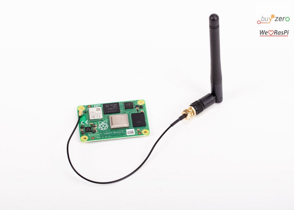
- on-board WLAN support (in WiFi versions), with PCB trace antenna and optional external antenna!
significantly simplified power supply design
You’ll be shocked how simple it is to design for the new Raspberry Pi compute module: one single +5V supply is all that is needed, and it will even supply up to 600 mA at 3.3V and 1.8V to peripherals for you.
No more adding different power rails & carefully sequencing them – this will greatly simplify your own carrier board design.
Pinout differences between Compute Module 4 and Compute Module 3
There are different groups of pins on the Compute modules, we’ll look at each of them and their differences between the versions in turn.
GPIO pin differences between the compute modules
In the table below, I’ve listed the available GPIO pins on compute module 4 (CM4), on compute module 3 (cm3), and on the Raspberry Pi 4, with their respective pin numbers.
GPIO pins are divided by GPIO banks, on the Raspberry Pi SoC, pins GPIO0 – GPIO27 are in GPIO Bank 1, whereas pins GPIO28 to GPIO45 are on GPIO Bank 2. The GPIO banks, on CM3, can be driven with independent voltages (GPIO0-27_VREF and GPIO28-45_VREF).
On CM4 and Pi 4 only the first GPIO bank (GPIO0 – GPIO27) are exposed. In addition to that, CM4 exposes GPIO44 and GPIO45, which are usually used for driving the official Raspberry Pi camera(s) and 7” display. The CM4 therefore lacks 16 GPIO pins in comparison to the CM3!
| GPIO BCM ID | CM4 Pin# | CM3 Pin# | Pi 4 Pin# | Note |
| GPIO0 | 36 (ID_SD) | 3 | 27 | ID_SD = SDA0 |
| GPIO1 | 35 (ID_SC) | 5 | 28 | ID_SC = SCL0 |
| GPIO2 | 58 | 9 | 3 | SDA1 |
| GPIO3 | 56 | 11 | 5 | SCL1 |
| GPIO4 | 54 | 15 | 7 | GPCLK0 |
| GPIO5 | 34 | 17 | 29 | GPCLK1 |
| GPIO6 | 30 | 21 | 31 | GPCLK2 |
| GPIO7 | 37 | 23 | 26 | SPI0_CE1_N |
| GPIO8 | 39 | 27 | 24 | SPI0_CE0_N |
| GPIO9 | 40 | 29 | 21 | SPI0_MISO |
| GPIO10 | 44 | 33 | 19 | SPI0_MOSI |
| GPIO11 | 38 | 35 | 23 | SPI0_SCLK |
| GPIO12 | 31 | 45 | 32 | PWM0 |
| GPIO13 | 28 | 47 | 33 | PWM1 |
| GPIO14 | 55 | 51 | 8 | TXD0 / TXD1 |
| GPIO15 | 51 | 53 | 10 | RXD0 / RXD1 |
| GPIO16 | 29 | 57 | 36 | |
| GPIO17 | 50 | 59 | 11 | |
| GPIO18 | 49 | 63 | 12 | PCM_CLK |
| GPIO19 | 26 | 65 | 35 | PCM_FS |
| GPIO20 | 27 | 69 | 38 | PCM_DIN |
| GPIO21 | 25 | 71 | 40 | PCM_DOUT |
| GPIO22 | 46 | 75 | 15 | |
| GPIO23 | 47 | 77 | 16 | |
| GPIO24 | 45 | 81 | 18 | |
| GPIO25 | 41 | 83 | 22 | |
| GPIO26 | 24 | 87 | 37 | |
| GPIO27 | 48 | 89 | 13 | |
| GPIO28 | 28 | SDA0 | ||
| GPIO29 | 30 | SCL0 | ||
| GPIO30 | 34 | |||
| GPIO31 | 36 | |||
| GPIO32 | 46 | GPCLK0 TXD0 / TXD1 | ||
| GPIO33 | 48 | RXD0 / RXD1 | ||
| GPIO34 | 52 | GPCLK0 | ||
| GPIO35 | 54 | SPI0_CE1_N | ||
| GPIO36 | 58 | SPI0_CE0_N TXD0 | ||
| GPIO37 | 60 | SPI0_MISO RXD0 | ||
| GPIO38 | 64 | SPI0_MOSI | ||
| GPIO39 | 66 | SPI0_SCLK | ||
| GPIO40 | 70 | PWM0 / TXD1 SPI2_MISO | ||
| GPIO41 | 72 | PWM1 / RXD1 SPI2_MOSI | ||
| GPIO42 | 76 | GPCLK1 SPI2_SCLK | ||
| GPIO43 | 78 | GPCLK2 SPI2_CE0_N | ||
| GPIO44 | 82 (SDA0) | 82 | cam / disp SDA0 / SDA1 GPCLK1 SPI2_CE1_N | |
| GPIO45 | 80 (SCL0) | 84 | cam / disp SCL0 / SCL1 SPI2_CE2_N |
There are two special I2C buses – one on GPIO0 and GPIO1, which is used for HAT EEPROMs (ID_SD / ID_SC), and one on GPIO44 and GPIO45, which is typically used to connect the camera and display.
Note also, that on CM4 you have the capability to set the GPIO output voltage, using GPIO_VREF – this can be connected to +1.8V or +3.3V for 1.8V or 3.3V signalling respectively. From the datasheet, it is unclear, however how this will affect GPIO44 and GPIO45, as they are in the GPIO Bank 1!
On CM4, GPIO2 and GPIO3 (used for I2C) have 1.8K pull up resistors.
Compute Module 3+ allows access to the SPI2 bus, which is not exposed anywhere else – on CM4, you will only have access to SPI0 and SPI1.
CM4 will not allow simultaneous access to UART0 (TXD0, RXD0) and the miniUART, UART1 (TXD1, RXD1). Here both are exposed on GPIO14 and GPIO15 as alternatives.
CM4, however, like the Raspberry Pi 4, includes additional UARTs (up to 6 UARTs in total), SPI ports (up to 6 SPI ports in total, five of which are exposed on Pi 4 and CM4) and I2C ports (up to 6 x I2C). These are available as additional pin mux options on the GPIO Bank 0.