Controlling LEDs on Alpine Linux using the command line
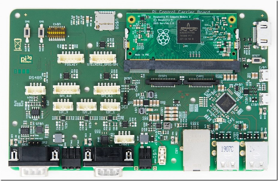
We have developed an embedded Raspberry Pi Compute Module carrier board for industrial use: the PCCB.
As you can see, there are three (directly) user programmable LEDs on the PCCB: USER / INFO / ACT.
These are defined in the device tree. For example, we can define the following in our device tree overlay:
//LEDs
fragment@11 {
target = <&leds>;
__overlay__ {
led_act: ledact {
label = “myledact”;
gpios = <&gpio 5 0>;
linux,default-trigger = “mmc0”;
};
led_info: ledinfo {
label = “myledinfo”;
gpios = <&gpio 16 0>;
linux,default-trigger = “cpu”;
};
led_user: leduser {
label = “myleduser”;
gpios = <&gpio 22 0>;
linux,default-trigger = “heartbeat”;
};
};
};
The device tree overlay source file (.dts) will need to be compiled, and will yield a .dtbo file.
This file is included as an overlay in the config.txt (in our case it actually is included in a subfile, usercfg.txt which is included from the config.txt)
# Pi Control Carrier Board Overlay
dtoverlay=pi-control-carrier-board
This will tell the VideoCore OS which is loaded first to pass on the device tree for the particular Pi model including our overlay to the Linux kernel.
What is a device tree?
ARM devices have become increasingly more customized and diverse as compared to standard x86 devices which had standarized components.
In order to avoid recompiling the kernel and having to match every single modified hardware, a system of describing the hardware layout to the Linux kernel was devised.
The device tree.
It is an OS independent concept, as it is loaded into the OSes Kernel. Any operating system which wishes to, can support it.
The Linux kernel will receive the device tree, and thus knows which device is present, how it is connected, and how to talk to it (drivers are loaded depending on hints in the device tree, for example).
As a Raspberry Pi is not static hardware, but it comes in different configurations & can expose different pins, for example, and also have different add-ons (HATs), an additional add-on was required: device tree overlays.
These files allow to modify the device tree, without having to have an individual new device tree for every possibly combination of hardware you can attach to the Pi / configure the Pi to.
How do I control the LEDs?
These LEDs will turn up in the system, in the /sys/class/leds directory:
As you can see, a total of four LEDs is exposed here, three of which (myledact, myledinfo, myleduser) were added by us using the overlay!
Each of these LEDs is a directory in of itself,
which gives you control over the LED.
Remember, in Linux everything is a file / talking to the kernel is abstracted to doing operations on the filesystem (it’s actually a UNIX paradigm).
Run
cat trigger
for the LED.
It will show you a list of which triggers can be set for it:
none rc-feedback kbd-scrolllock kbd-numlock kbd-capslock kbd-kanalock kbd-shiftlock kbd-altgrlock kbd-ctrllock kbd-altlock kbd-shiftllock kbd-shiftrlock kbd-ctrlllock kbd-ctrlrlock timer oneshot heartbeat backlight gpio cpu cpu0 cpu1 cpu2 cpu3 default-on input panic [mmc0]
Note that the last trigger, mmc0 is in square brackets. This is what the LED is currently set to!
You can try setting it to any of the other triggers by writing this trigger to the LED (if you have sufficient rights ![]() ):
):
echo “timer” > trigger
Will make the LED blink.
Note, if you now list the LED control directory again, you’ll see additional entries – new functionality which is exposed for the timer mode:
delay_off and delay_on
cat delay_off
yields 500. These are 500 milliseconds.
You can adjust these values to make the LED blink faster, for example:
echo “150” > delay_off
echo “150” > delay_on
Or slower …
echo “1500” > delay_on
echo “1500” > delay_off
A couple of noteworthy triggers:
- none: there is no activity on the LED
- mmc0: is active if the Flash / microSD is being accessed
- cpu: is active with CPU activity (nice to monitor how busy the CPU is, as it will be kind of dimmer if there’s less CPU activity, thanks to effectively a kind of PWM)
- heartbeat: will give a steady blink pattern to show the Pi is still live and the kernel is still online and doing it’s work.
Controlling the LED GPIO from my own code?
To control the LEDs from your own code, using GPIO libraries, set the trigger to “none”.
echo “none” > trigger
You can still turn it on and off from the command line, by writing to brightness (1 to turn it on, 0 to turn it off):
echo “1” > brightness
echo “0” > brightness
Now you’re able to control an LED from the command line ![]() And you’ve learned something about device trees and device tree overlays, congratulations!
And you’ve learned something about device trees and device tree overlays, congratulations!


