
CM5 / Broadcom BCM54210PE Ethernet Voltage drive mode and center tap design
We are currently working on a CM5 PCB design. For the Ethernet part, a decision has to be made about the center tap design. Unfortunately, the Broadcom BCM54210PE datasheet is not public.
TL;DR
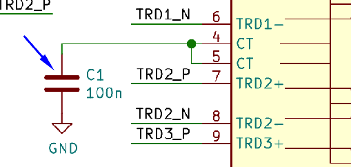
The center tap for a CM5 / BCM54210PE design should not be biased with any voltage. Use a 100n capacitor against GND for it. Follow the design suggested by Raspberry Pi CM5 datasheet (page 8). This is irrespective of whether you are designing for PoE capability or not.
Background on center taps and PHYs
There are two types of PHYs which determine, how the center tap needs to be connected.
- current mode PHYs
- voltage mode PHYs
Current mode PHYs require the center tap to be connected (biased) to VDD. The bias will define the voltage the DC level the signal swings around. Without the bias, you will get poor signal integrity, and an undefined common mode.
Voltage mode PHYs do not require the center tap to be connected to VDD. The center tap is only used for AC common mode termination. In fact, applying a DC bias will fight the internal bias and introduce unwanted distortions to the signal.
Ref:
- https://support.microchip.com/s/article/Design-Guidance-on-Current-Mode-and-Voltage-Mode-PHYs–Center-Tap-of-Transformers
- https://www.linkedin.com/pulse/phymagnetics-interface-small-detail-can-break-your-ethernet-kagan-m7sef/
Broadcom BCM54210PE PHY voltage drive mode
We do not have the BCM54210PE datasheet, as it is not public. However, there are important and conclusive hints given by Raspberry Pi engineers.
The BCM54210PE PHY is used both in the CM4 and CM5:

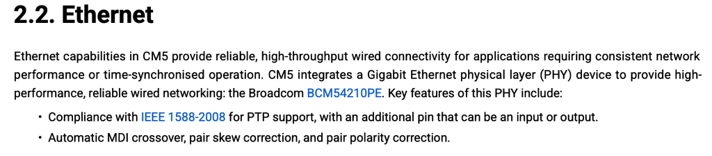
Keeping that in mind, we get information from a Raspberry Pi engineer (dp11) in the Raspberry Pi Forum for a CM4 design:
“If you use a mag jack compatible with A70-112-331N126 then you don’t need any extra parts. The phy has voltage mode drive instead of current mode.”
This refers to the same PHY, the BCM54210PE, used on CM5.
In other words: the Broadcom BCM54210PE PHY, as confirmed by a Raspberry Pi engineer, has voltage mode drive. This means, no voltage bias on the center tap! Whether you are designing for a CM4 or CM5.
Ref:
As additional proof, both Raspberry Pi data sheets show the center tap not being connected to any voltage bias:
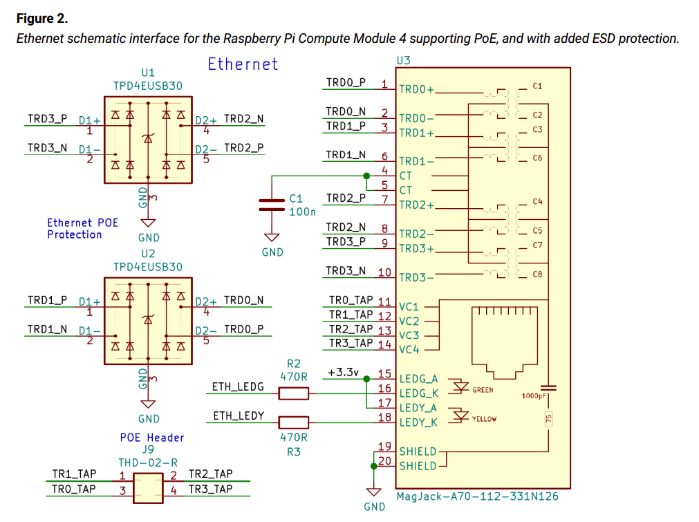
on CM5:
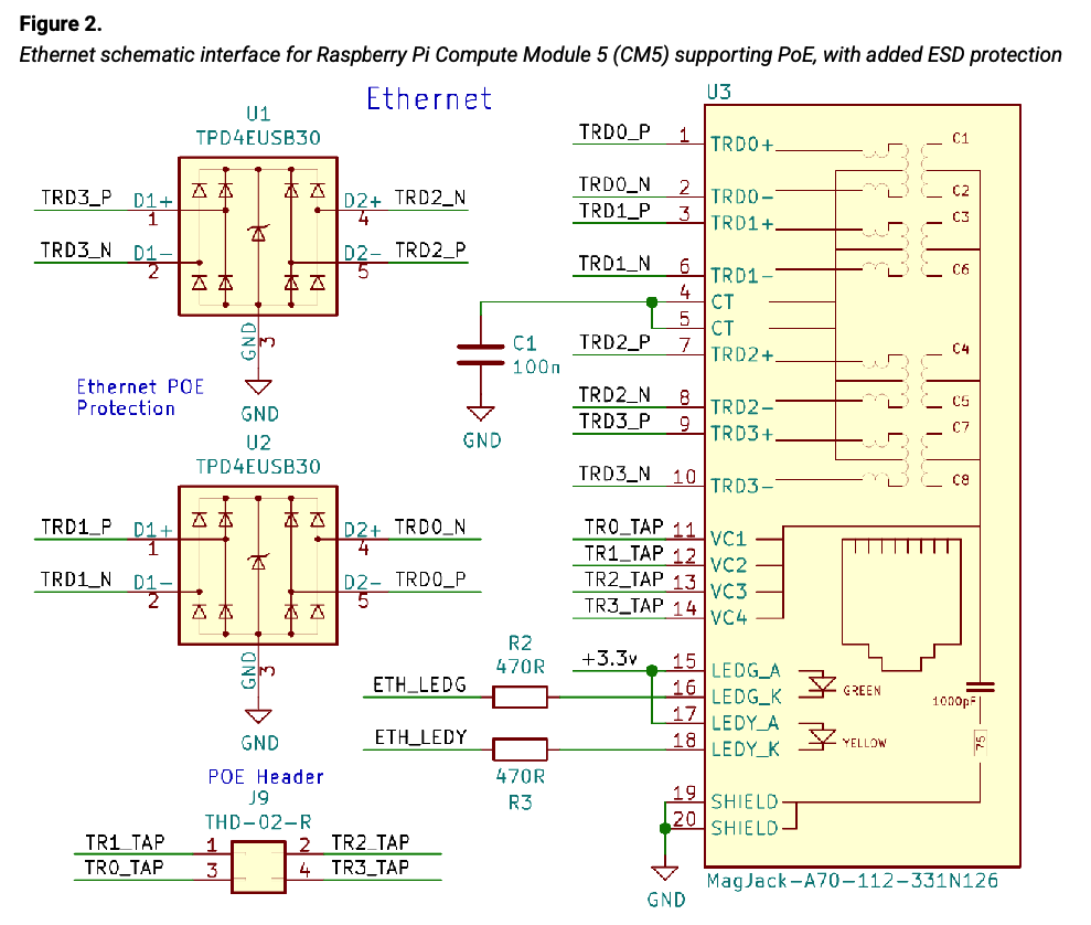
This, of course, is a reference design for a PoE-enabled carrier board. There is an argumentation by some engineers that the center tap is somehow related to it.
However, consider the situation where PoE is designed-in, but optional, as on a Pi 5, or CM5 carrier board. The design naturally must cover this case as well.
To summarize: simply follow the design suggestion in the Raspberry Pi CM4 or CM5 datasheet. Do not bias the center tap, connect it to a 100n capacitor (C1 in the images) against GND.
 English
  Deutsch (Sie)